

In a previous post I explored a technique to connect a chain of LEDs in parallel and enable the LEDs to blink alternatively in a series of animations using an H-Bridge. Since the H-Bridge is used extensively in motor controllers, in this post I take the experiment one level further and use an integrated motor controller to drive the LED chain.
GOAL
Using what was learned from the LED Chain Driver experiment – it should be possible to use an integrated motor controller and create the same animated effects with a chain of LEDs that are connected to a two wire bus in alternate directions.
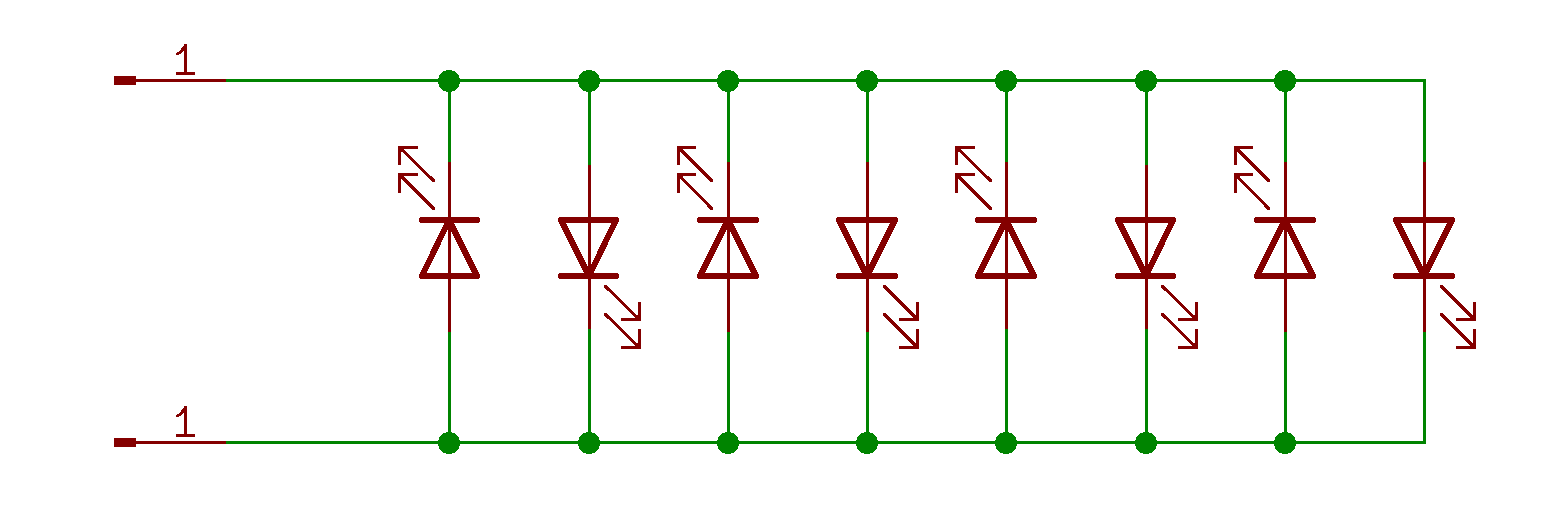
Fig 1. The connection of the LEDs.
METHOD
Equipment
- Teensy LC.
- Integrated Motor Controller.
Connections
It is always fun to use for other experiments and purposes. I had implemented a motor controller a while back for the 2016 revision of Contextual Electronics – The Go, go, go! project. This project used a TB6593FNG integrated motor controller. I checked the specifications of this chip and was confident it would be able to handle the loads that I was intending to use with ease. All I needed then was a microcontroller. For this purpose, I used a Teensy LC that I had available.

The connections were made as per the Fritzing diagram below. The Teensy was powered and programmed through its USB connector to the PC. The motor controller board was powered through a 9V battery with an adapter attached and configured to 3.3V. Out1 and Out2 from the motor controller board were connected to the bus lines of a breadboard. LEDs were arranged on the bus lines in an alternate configuration of anodes and cathodes.
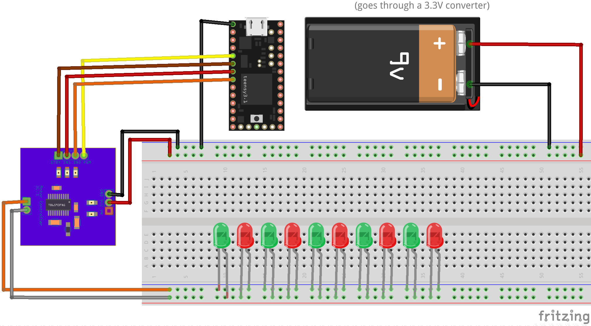
The four control lines between the Teensy and the motor controller board were connected as shown in Table 1.
| Teensy Pin | Motor Controller Board |
| 3 | PWM |
| 4 | Stand by |
| 5 | In1 |
| 6 | In2 |
Firmware
I based the firmware off one of the original test programs for the Motor Controller project. I figured this would be the easiest place to start as it uses the Arduino library with the Teensy LC. This sample was then expanded to encompass the animations created for the original LED Chain driver project.
The original approach to control the discrete components version of the H-Bridge used a PWM signal to control the enabling of the respective banks of LEDS. At that stage I did not consider any additional PWM for the intensity of the LEDs. When driving the LEDs through the motor controller, I have a PWM signal to control the intensity of the LEDs but no clear means to toggle between the respective banks of LEDs. The solution I came up with was to utilise two interrupting timers in the Teensy. One controlled the enabling of the LED banks, whose configuration was changed depending on the effect – slow side to side blinking (5 – 10 Hz) or 100Hz to create a persistence-of-vision effect so that all LEDs are perceived to be on at the same time. The other timer provided a one second pulse to keep track of the duration for the various animation effects.
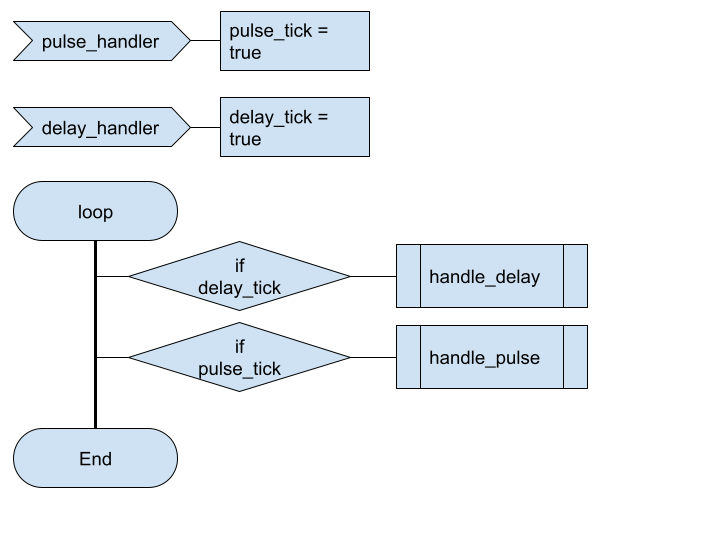
Figure 4. depicts a part of the algorithm where the respective interrupt handler routines set a flag. These flags are checked in the main loop. When “delay_tick” is set to true, then the delay handler is called. The delay handler is responsible for monitoring the length of time an effect is running for and for selecting a new effect when the time has expired. The new effects are randomly selected as is the duration. The effect selected would dictate what the pulse timer should be set to i.e. 5Hz, 10Hz or 100Hz. The pulse timer handler, called when the pulse_tick is set to true, is responsible for the setting of the intensity of the LED via the PWM value and enabling the appropriate LED bank.
Once the firmware was working for the basic set of animations, they were expanded to take advantage of the PWM signal that was not available in my original project. This meant I could introduce LED breathing effects. Table 2. describes the attempts and the signal usage.
| Function | Discrete component H-Bridge | Motor controller |
| Driving the LEDs | The PWM signal is applied to the enable input of the JK flip flop . | Explicitly driving the Input 1 and input 2 using an interrupt timer. |
| Changing the LED blinking frequency | Change the value of the PWM signal. | Change the frequency value of the timer interrupt. |
| Alter the LED intensity | Not supported. | Alter the PWM signal to the motor controller. |
Results
All the animation effects created for the original project using the discrete component H-Bridge were able to be implemented using the motor controller. The motor controller variant gave an additional feature of being able to control the intensity of the LEDs. This was not possible with my implementation of the H-Bridge.
The simple approach to controlling the intensity of the LEDs, although the values were set in a linear fashion, the effect on the eye was not uniform and gave a perceived bouncing effect.

Since the effect of the LEDs did not give the impression of a Sine pattern. An additional experiment was made to convert the PWM values into their sine equivalents in order to provide a more uniform breathing effect. The PWM value was remapped such that 0 -> 255 became 0 -> 90 degrees. To save CPU cycles, the values were calculated out and added as an array of uint8_t in the firmware.
| PWM | Sine Equiv |
| 0 | 0 |
| 5 | 0 |
| 10 | 0 |
| 15 | 2 |
| 20 | 3 |
| 25 | 5 |
| 30 | 8 |
| 35 | 11 |
| 40 | 15 |
| 45 | 19 |
| 50 | 23 |
| 55 | 28 |
| 60 | 33 |
| 65 | 38 |
| 70 | 44 |
| 75 | 50 |
| 80 | 56 |
| 85 | 63 |
| 90 | 70 |
| 95 | 77 |
| 100 | 84 |
| 105 | 92 |
| 110 | 99 |
| 115 | 107 |
| 120 | 115 |
| 125 | 123 |
| 130 | 131 |
| 135 | 138 |
| 140 | 146 |
| 145 | 154 |
| 150 | 162 |
| 155 | 169 |
| 160 | 176 |
| 165 | 184 |
| 170 | 191 |
| 175 | 197 |
| 180 | 204 |
| 185 | 210 |
| 190 | 216 |
| 195 | 221 |
| 200 | 226 |
| 205 | 231 |
| 210 | 236 |
| 215 | 240 |
| 220 | 243 |
| 225 | 246 |
| 230 | 249 |
| 235 | 251 |
| 240 | 253 |
| 245 | 254 |
| 250 | 255 |
| 255 | 255 |

CONCLUSION
The overall results of driving the LEDs through a motor controller were consistent with the original attempt with the H-bridge using discrete parts. The advantage seen with using the motor controller was that it was now possible to implement some LED breathing effects where the intensity of the LEDs slowly increased and decreased.
When setting the values of the PWM in a linear fashion, the end result of the breathe effect is not uniform. When the values were converted to follow a sine pattern, there was an improvement but there was a feeling that the effects were still not uniform. Further adjustments to these calculated values would be required to achieve a better result. However, this was not the purpose of this experiment.
