I wanted to learn how to use a 128×64 pixel display, i.e. the DOGM-128-6 from Display Visions. I then got distracted by the requirements of the LED backlight. For several of the backlight options they suggest some series current limiting resistors for 3.3V and 5V. For the White, Blue and Full Colour backlights, they suggest using the CAT4238. I could not locate this device through my usual suppliers so I decided to see how far I could get with something that I thought was similar. I opted for the BCR421UW6. In this post I describe how I went about testing the device to get a better understanding of its use and if this would be a good fit for the intended purpose.
I have been working on a new project idea. A device that could check the continuity and connections of a series of cables – namely the coaxial cables connecting LNBs on a satellite dish to the multi-switch. For this I need to drive several channels. In working through the design I wanted to explore two approaches. One approach uses encoders/decoders. The other approach uses shift registers. This gave me the opportunity to take advantage of a new addition to my bench – a MaxiMite 2 compact computer. In this post I will describe the two approaches and my first impressions of the MaxiMite 2 for the purpose of prototyping.
The local open lab sent out a call for ideas to run workshops over the lead up to Christmas. I thought of a Christmas tree with candlelight LEDs. I needed to know what was involved in making such a model before I could conduct a workshop. In this post I describe the that approach that I took and the improvements I came up with as a a result of trying it out first hand.
I became interested in a LED display I saw in a beer garden over Summer. The remarkable thing was that it was clearly LEDs on a bus of only two wires. Even so the LEDs were able to be animated such that they could blink in unison or every other alternatively. I was intrigued as to how this could be done.
The purpose of this project was to come up with a means to to alternately blink a chain of LEDs either in unison or alternately using only two wires. During the development, what I had not realised until quite late was, I was actually using a H-Bridge
I have looked into using Neo-pixels strips and I was really impressed with the simplicity of use. Now I was curious about controlling a matrix of individual, non-addressable RGB LEDs. So I searched out a LED Matrix driver that looked like it could handle RGB LEDs. My search ended with the IS31FL3736 12×8 DOTS MATRIX LED DRIVER WITH INDIVIDUAL AUTO BREATH FUNCTION. This seemed to have the features I wanted to start out with and did not require me to install masses of LEDs. This is a note about what I learned along the way.
For a while now I have been intrigued with Integrated Light Sources i.e. NeoPixels. I knew nothing about them and with the coming of Christmas, I was inspired to take a closer look. I knew I would not have anything in place before Christmas 2017. But there is always next year.
I recently had the opportunity to revisit an old project of a doorbell extension that
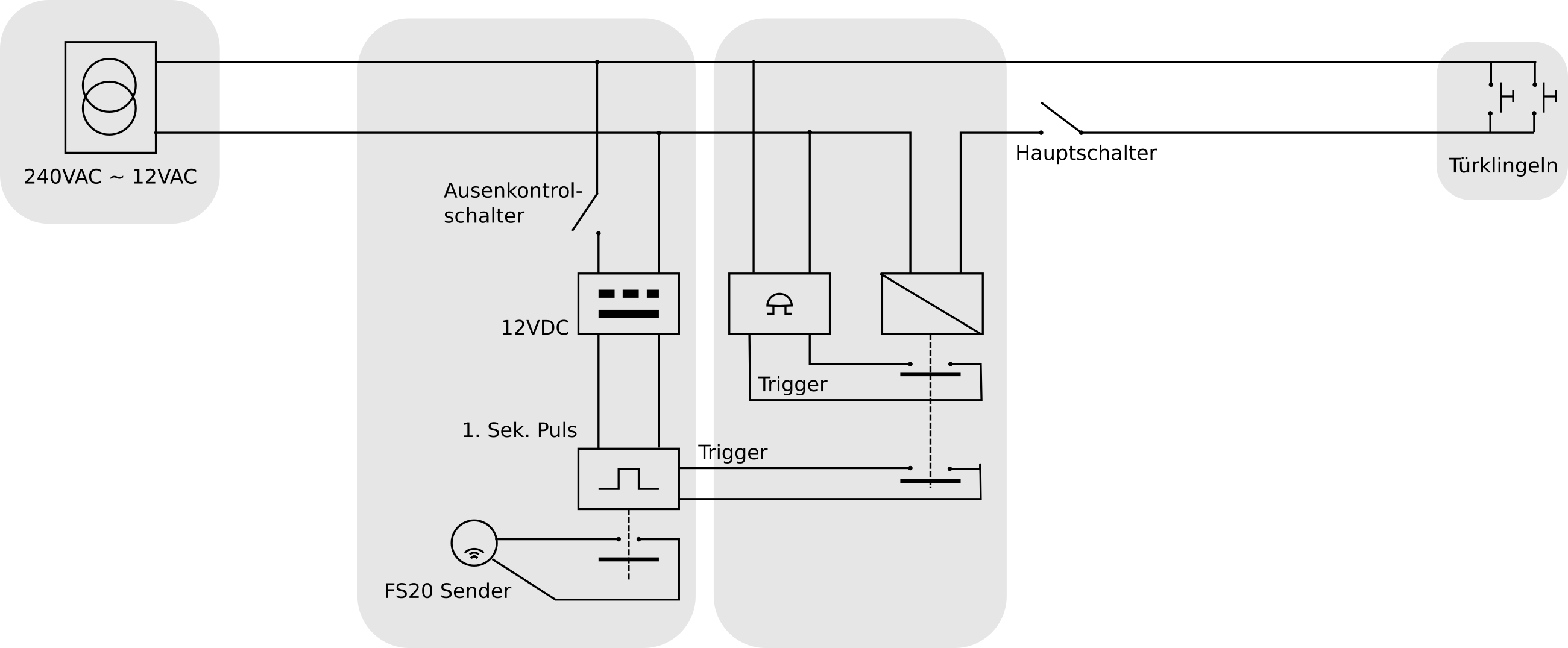
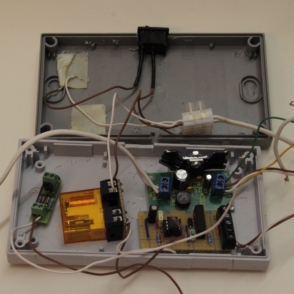
used the ELV FS20-S4SUB to send a signal to the ELV FS20 SIG-2. At the time I did this with what I knew at the time to get the job done with the equipment I had. This meant nothing too sophisticated. Pretty much off the shelf modules for the “ELV Universal-Spannungsreglerplatine Komplettbausatz” as DC power supply, a 8 DIL 555 timer as a one-shot mounted on vero board. It certainly did not look nice and I knew there would be a better way, but it worked.
In this original implementation, I had to go to these lengths of using the relay and oneshot as I found connecting a relay directly to the doorbell switch to drive the FS20-S4SUB was not reliable and needed a way to denounce the press button as well as being on long enough to trigger the FS20-S4SUB.
After four years of working without a hitch, this project was brought back to my attention, so I decided to redo this with what I know now. The major criteria is that I should not spend too much time on this. I had two choices 1) Go with with I have already done 2) move to an embedded solution. While 2) could be fun and would be more compact, I decided on option 1 since I could reuse the ELV FS20-S4SUB, which was still serviceable. All I needed to do was model the existing solution in KiCad as a single board.
New Design
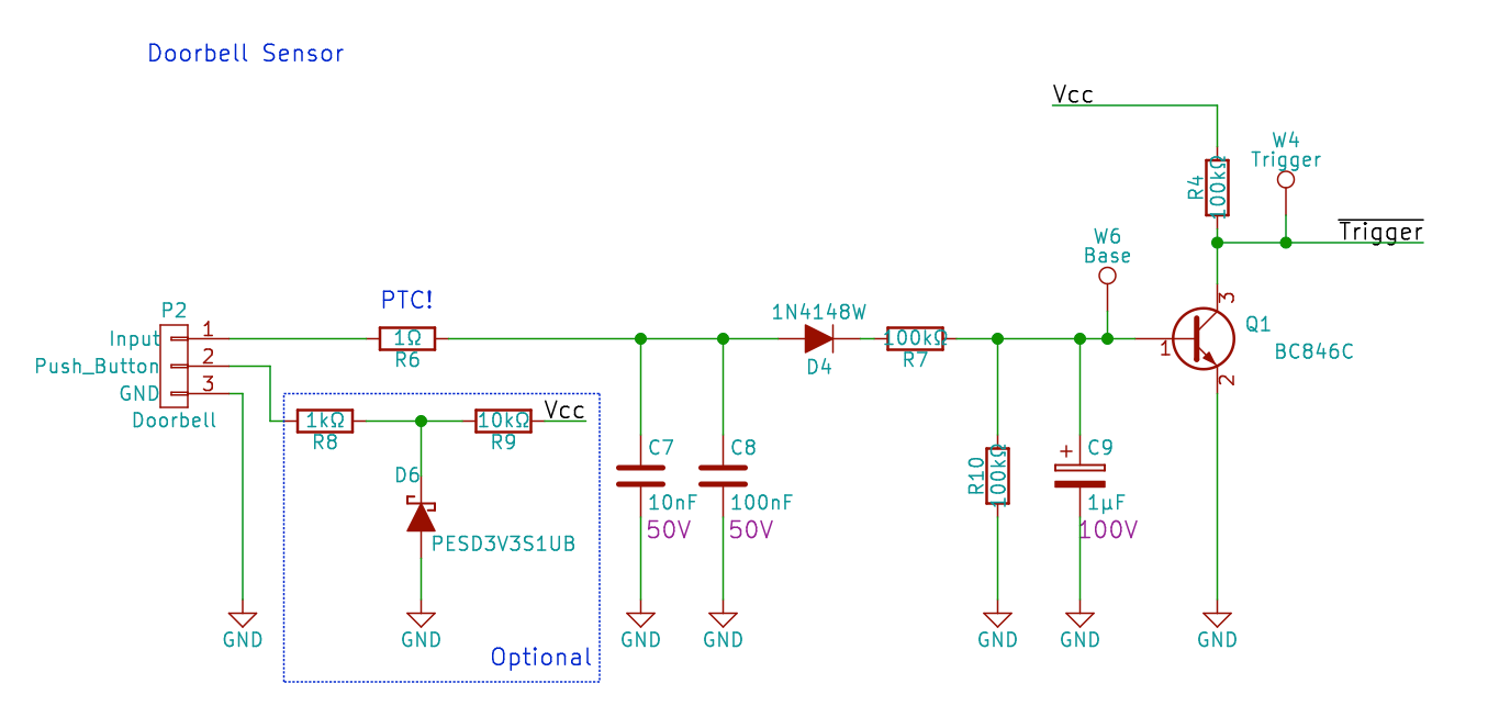
As shown above, the existing solution was based on relays. I didn’t want to bring these forward into the new design. There is an interesting solution put forward in ELV 06/2014 whereby they implement a door bell sensor by feeding the rectified signal into the base of a transistor (pins 1 and 3 of P2). Their solution also provided an addition possibility by sourcing the voltage as well so that a stand-along press button could be used (pins 1 and 2 of P2).
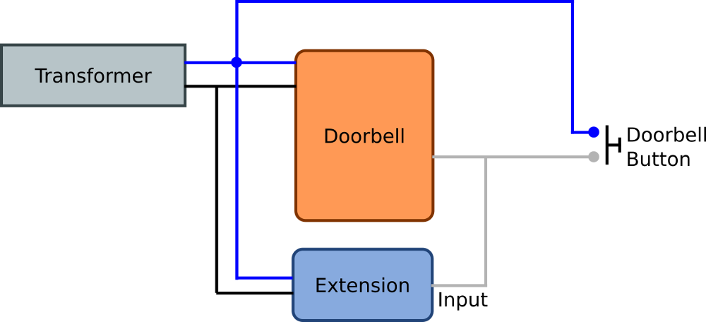
Here most doorbells are powered by a transformer delivering between 8 to 12V. So this system was designed sense the voltage from the doorbell button whereby the device itself is battery powered and the doorbell system is sourced by a 12V transformer. In my case I would be powering the device from the same transformer as I have done in the original solution, thereby saving the need to change batteries.
The part that was bugging me was the interface to the FS20-S4SUB. My first approach to this problem was to simply use the same reed relay. But in examining this set up, I started to have doubts about what I was actually doing in the original design.
My first problem was the power. The transformer is delivering about 15 Volts without load. I originally had set up the DC power supply with a LM7812. Everything worked fine, but in this design, there is no room for any error or movement. Something I had not considered before. After speaking with my tutor, Chris Gammell of Contextual Electronics, he confirmed the doubt. Under load, if the transformer voltage would go below 12V, there could be a chance of a “drop-out”. He suggested bringing the supply voltage down to 9V, which would be more reliable. The main reason for sticking with 12Volts was the availability of cheap reed relays. I had trouble finding anything for 6V. Chris suggested the use of an Opto-Coupler in place of the reed relay.
Choosing the Opto-Coupler
I decided to embrace the Opto-Coupler suggestion since it would solve the power supply issue. But I had to familiarise myself with Opto-Couplers where I have never had reason to implement one before. The FS20-S4SUB has five wires. One Ground and four inputs, presumably open-collector with internal pull-ups. The problem now was finding a suitable Opto-Coupler. The resources I was finding on the web all seemed to be from the perspective of driving some load through the collector-emitter side and would then base their calculations on that current flow.
Placing a DMM across the contacts, I see 2.9Volts @ 0.03mA. It seemed to me that I could place almost any Opto-Coupler there. I decided to take the selection the other way. I intend to drive the LED at 10mA (though the rated maximum will probably be 40mA). From that, I need to only ensure 0.03mA can be seen at Ic, I figured a current transfer rate of 50%@5mA will be more than enough.
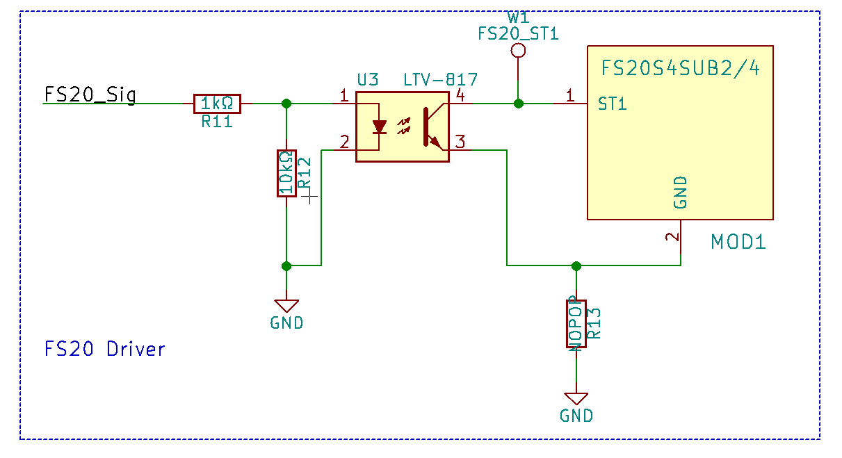
Interestingly enough, this criteria ushered me to the LTV-817S, which I had been seeing in lots of places as a standard, easily available part. So I presumed this to be a good place to start.
The circuit above shows the implementation I will be using. The 1KΩ R11 is used to limit the current to the LED. The 10kΩ R12 is used to pull the value on the LED down to ground when not active. R13, which is marked as “NO-POPulate” is there was a “Just-in-case” 0Ω or Jumper in case I may need to tie the FS20-S4SUB ground to the system ground.
putting it all together
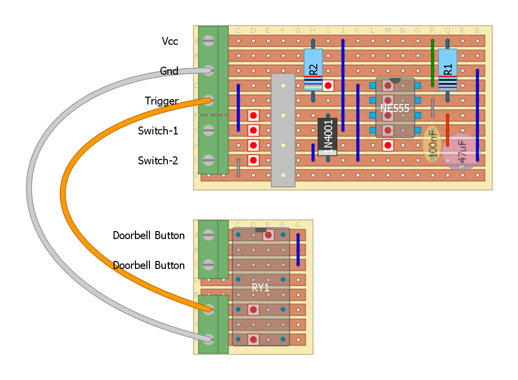
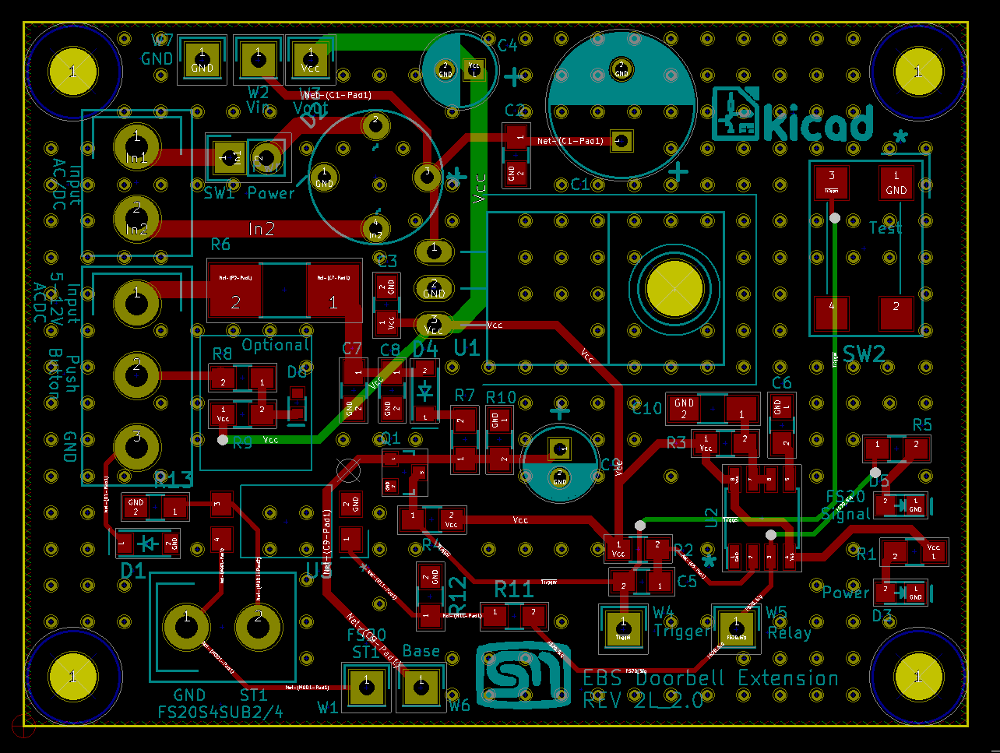
I took the liberty of compiling what were separate modules onto one board to create a self-contained solution and minimise its overall size. The layout below shows the remodelled DC Power supply, using a bridge rectifier and a LM7809 based on the ELV DC power supply, the One-shot trigger, using a SMD 555 timer and instead of the reed relay, the LVT-817S is used. Instead of the bulky relay as seen in the photo above, will be the door bell sensor as showcased in the ELV HomeMatic®-Funk Klingelsignalsensor. Some additional enhancements that were not included on the original design are some test points for verifying the behaviour and an indicator LEDs to indicate power-on and to show when the FS20-S4SUB should be sending its signal.
Revision 2
The Gerbers for the board was sent off to OSH Park and a couple of weeks later, The first set of prototype boards arrived. I ran into a small issue with my footprints. This has happened before where a I model the footprint as per the data sheet. However, there is a margin of error in the holes required for the leads and a margin of error for the holes drilled by OSH Park. Neither are wrong. It is just that one should take that into account and model the holes on the larger side. As it was, it was not too bad since I could solder some leads in the holes for the rectifier bridge and solder the rectifier bridge to the leads. The result looked quite neat.
Bringing the board up went smoothly and all aspects of the device tested out fine including driving the FS20-S4SUB through the Opto-Coupler.I was confident with the board that I proceeded with the second and final revision – the layout is shown above.
The connection of the device can be configured in a couple of ways which was a offshoot of using mechanism provided in the door bell sensor. However, I was only intending to use the configuration where by I power the system from the existing doorbell transformer and only need then the return wire from the actual doorbell switch.
Assembly
I found an appropriate case which happened to fit the board just nicely. Since I was using SMD LEDs for the indicators, I had the challenge of trying to work out where I should drill the holes for the Light-Pipes. I then decided to sacrifice a couple of the light pipes. Since Osh Park send three boards, I took one of the spare boards and hot glued the light pipes to the footprint location for the LEDs. I then coloured the tops with some ink and placed the cover in place. This provided some marks on the inner side of the casing and a closer than rough indicator as to where to drill.
Hot glued Light-Pipes
Snake-bite showing where to drill
The end result I considered was very good. The light pipes pick up the individual LEDs very well. I have put aside the light-pipes that I used to locate the holes in case I need them again one day.
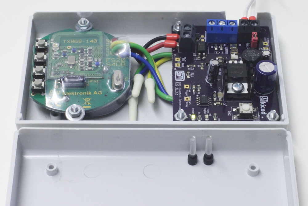
I have now the completed board and the FS20-4SUB neatly in the casing. I shortened the leads for the GND and TA1 on the FS20-4SUB but I still don’t have the heart to cut back the leads for the unused channels.
Conclusion
It was a lot of fun and very rewarding to revisit this old project. It is especially rewarding to compare what I knew then to what I have learned since then.
One of the goals was to see how quickly this could be completed. The first commit on Git-Hub was June 5, 2016 and I am writing this 49 days later (1 month, 2 weeks and 5 days), I did not record actual time spent on the project. I will leave that discipline for another project. This time includes the turnaround for two revisions of the board. Going through the BOM and adding up the parts used in the final device, the cost comes to 19,09€.


 I recently had the opportunity to revisit an old project of a doorbell extension that